Long Range Communication with ESP32 and RYLR993 LoRa Modules
![]()
Introduction
In this tutorial, you’ll learn how to create reliable long-range, low-power wireless communication between two ESP32 S3 Mini 1 boards using RYLR993 LoRa modules. This method doesn’t rely on WiFi or Bluetooth, making it great for places without regular internet access.
The goal is to make LoRa communication easier to understand and more approachable for students and developers who are new to the technology. Readers will get practical experience wiring the modules and using AT commands to send and receive data.
Learning Objectives
- Set up communication between two ESP32 S3 Mini 1 boards using RYLR993 LoRa modules
- Wire the hardware correctly and verify serial connections
- Use AT commands to configure and test LoRa modules
- Write Arduino code to send and receive messages over LoRa
- Monitor communication using the Serial Monitor
Background Information
LoRa stands for Long Range. It is a wireless communication protocol designed to send small amounts of data over large distances using very little power. This makes it useful in places where WiFi or cellular is not available.
The RYLR993 module handles the complexities of radio communication, so all you need to do is send it simple AT commands over serial. This means you don’t need advanced radio knowledge to get started.
LoRa is a good choice when:
- Data is small and does not need to be sent constantly
- Devices are far apart
- Power consumption needs to be low
- There is no existing network infrastructure
Compared to WiFi or Bluetooth, LoRa is slower but can reach much farther. It also works well with battery powered devices that need to last a long time without charging.
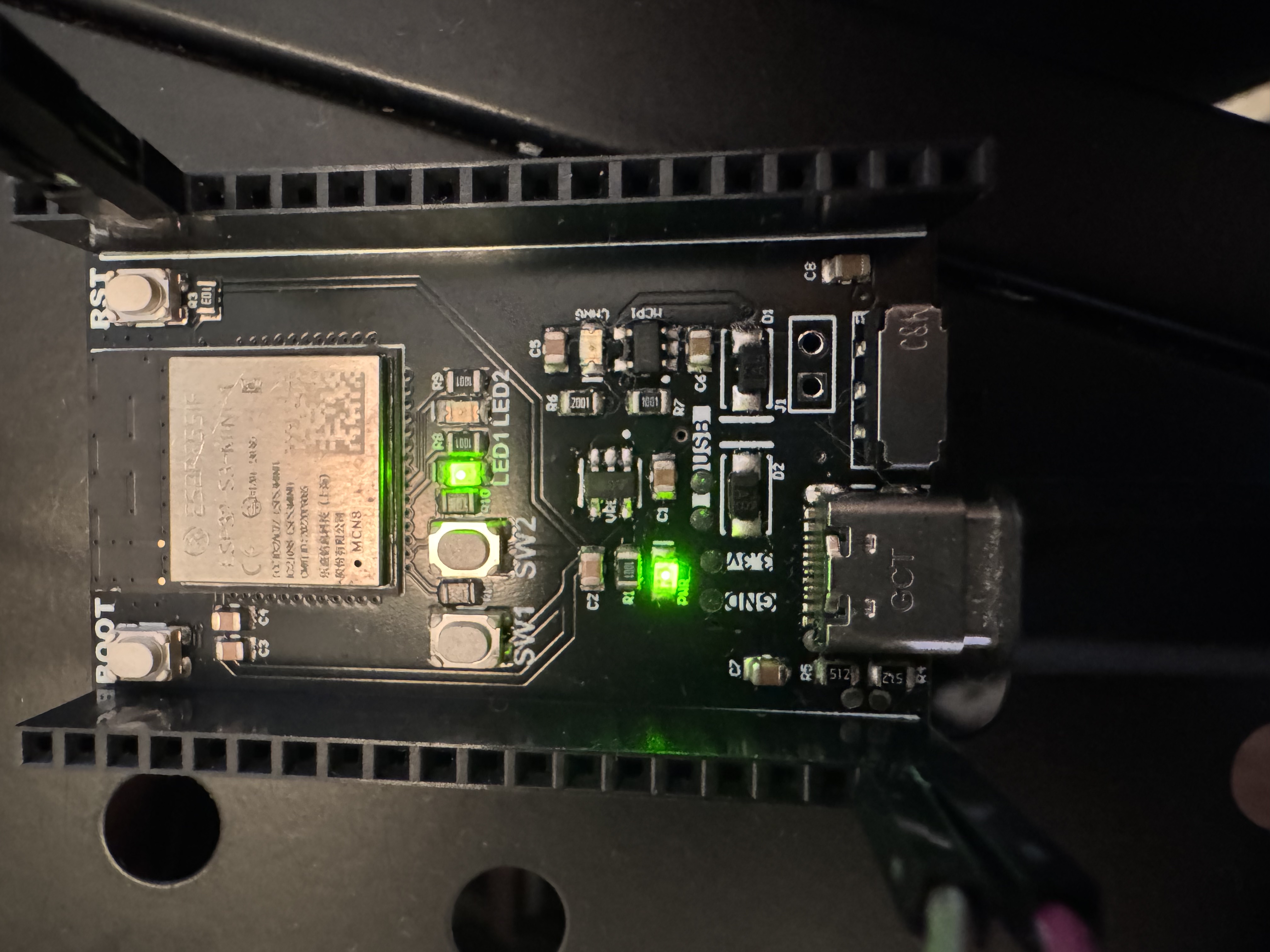
This tutorial uses the ESP32 S3 Mini 1 board because it is small, easy to program, and powerful enough to handle real world tasks. It also supports USB programming which simplifies setup.
Getting Started
To follow this tutorial, a few tools and files need to be installed. This section explains how to set up the development environment and prepare the hardware. All tools used are free and open source.
Required Downloads and Installations
Arduino IDE
This is the development environment used to write and upload code to the ESP32. Download it from: https://www.arduino.cc/en/softwareSerial Monitor
This comes built into Arduino IDE and will be used to view messages sent and received over LoRa.
Required Components
| Component Name | Quantity |
|---|---|
| ESP32 S3 Mini 1 | 2 |
| RYLR993 LoRa Module | 2 |
| Breadboard | 2 |
| Jumper Wires | 10 |
| USB-C Cable | 2 |
| USB-C power source | 1 |
Required Tools and Equipment
- Computer with USB-C port
- Arduino IDE installed
- Internet access for installing packages
- External USB-C power source for second ESP32
(such as a USB-C power bank or a second computer)
Part 01: ESP32 and LoRa Hardware Setup
Introduction
Here you’ll wire each ESP32 S3 Mini 1 to its own LoRa module. Proper wiring ensures stable power and smooth communication later when sending and receiving messages.
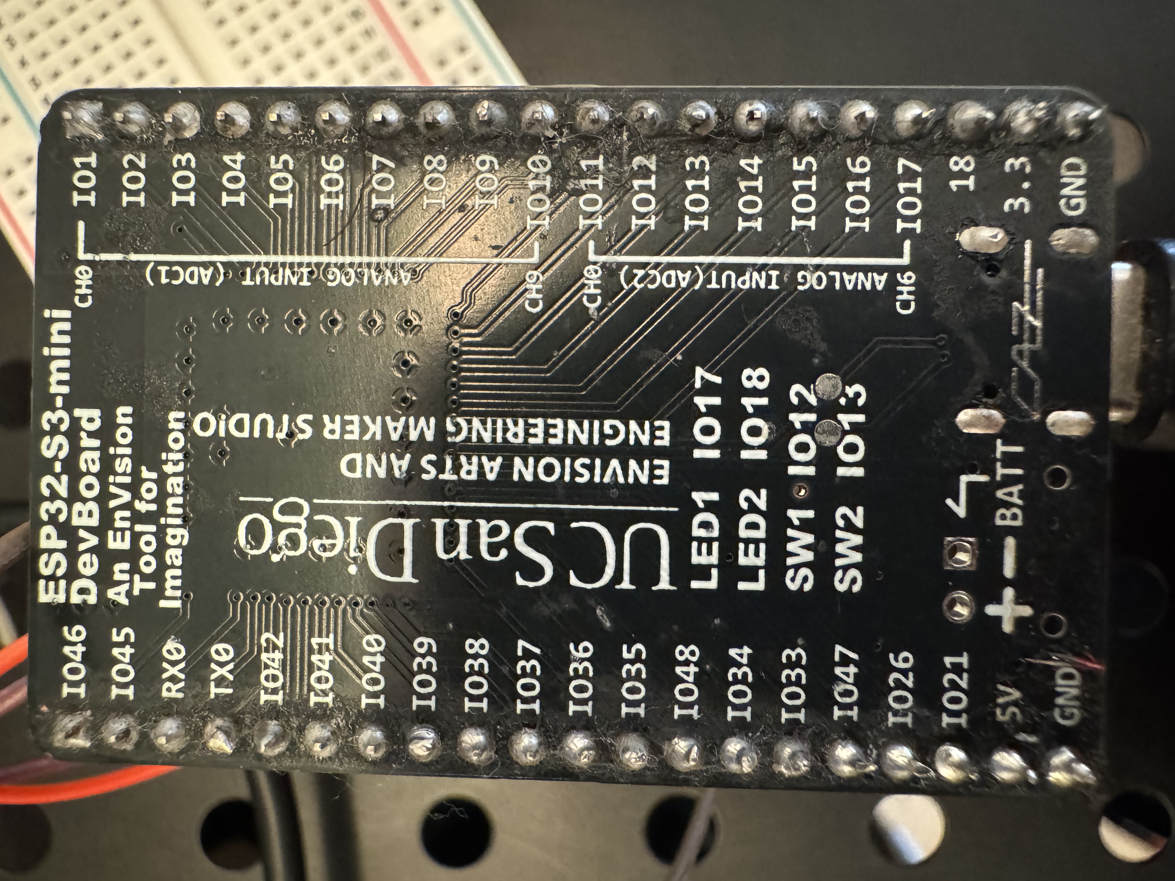
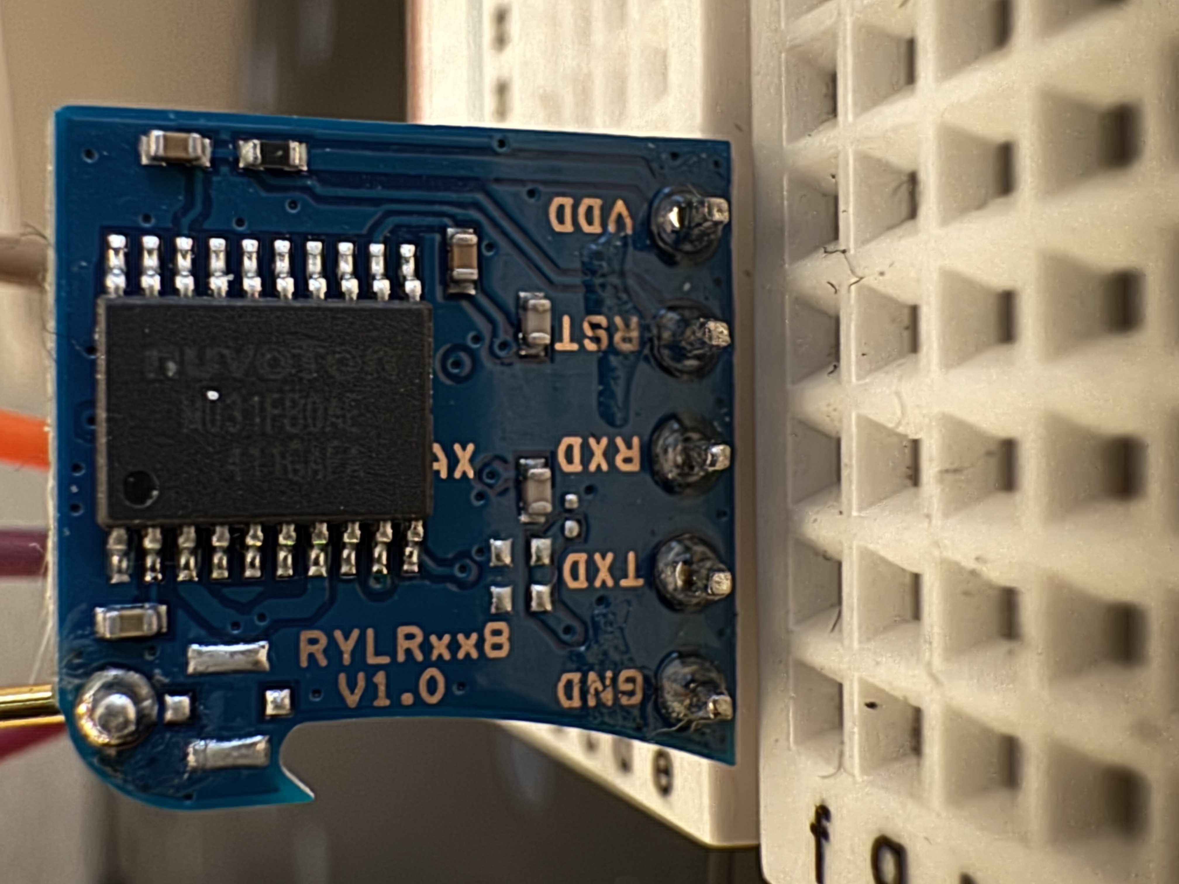
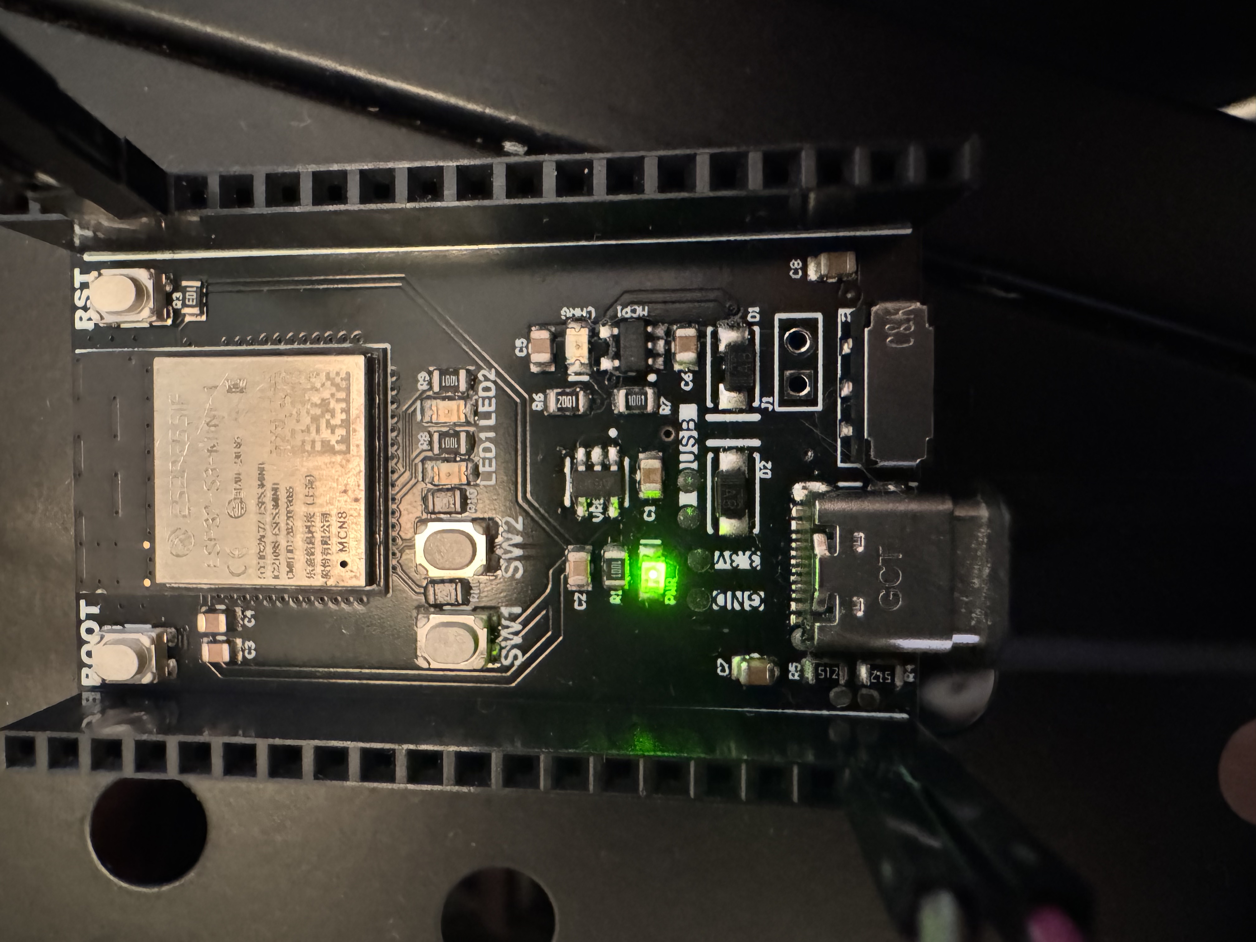
Photos below show the labeled pins on the underside of the ESP32 S3 Mini 1 and the layout of the RYLR993 LoRa module, including GND, TXD, RXD, RST (not used), and VDD.
Objective
- Connect each ESP32 S3 Mini 1 to its own RYLR993 LoRa module
- Match the correct UART pins for TX and RX
- Provide stable power using the 3.3V and GND lines
- Confirm that both modules are physically ready for communication
Background Information
The RYLR993 module uses UART to communicate with the ESP32. This means one wire will be used to transmit data (TX) and another to receive data (RX). Each ESP32 will need to be connected to its LoRa module using the correct TX and RX pins, along with 3.3V for power and GND for reference.
The default hardware UART on the ESP32 S3 Mini 1 is located on RX0 and TX0, which are clearly labeled on the bottom of the board. The RYLR993 has five pins: GND, TXD, RXD, RST (not used), and VDD. These must be connected properly for the module to receive power and pass data.
Wiring each module correctly now avoids problems later during testing and transmission.
Components
- 2 ESP32 S3 Mini 1 boards
- 2 RYLR993 LoRa modules
- 2 Breadboards
- 8 Male to Male jumper wires
- 2 USB-C cables
- 1 USB-C power bank or second USB-C computer port
Instructional
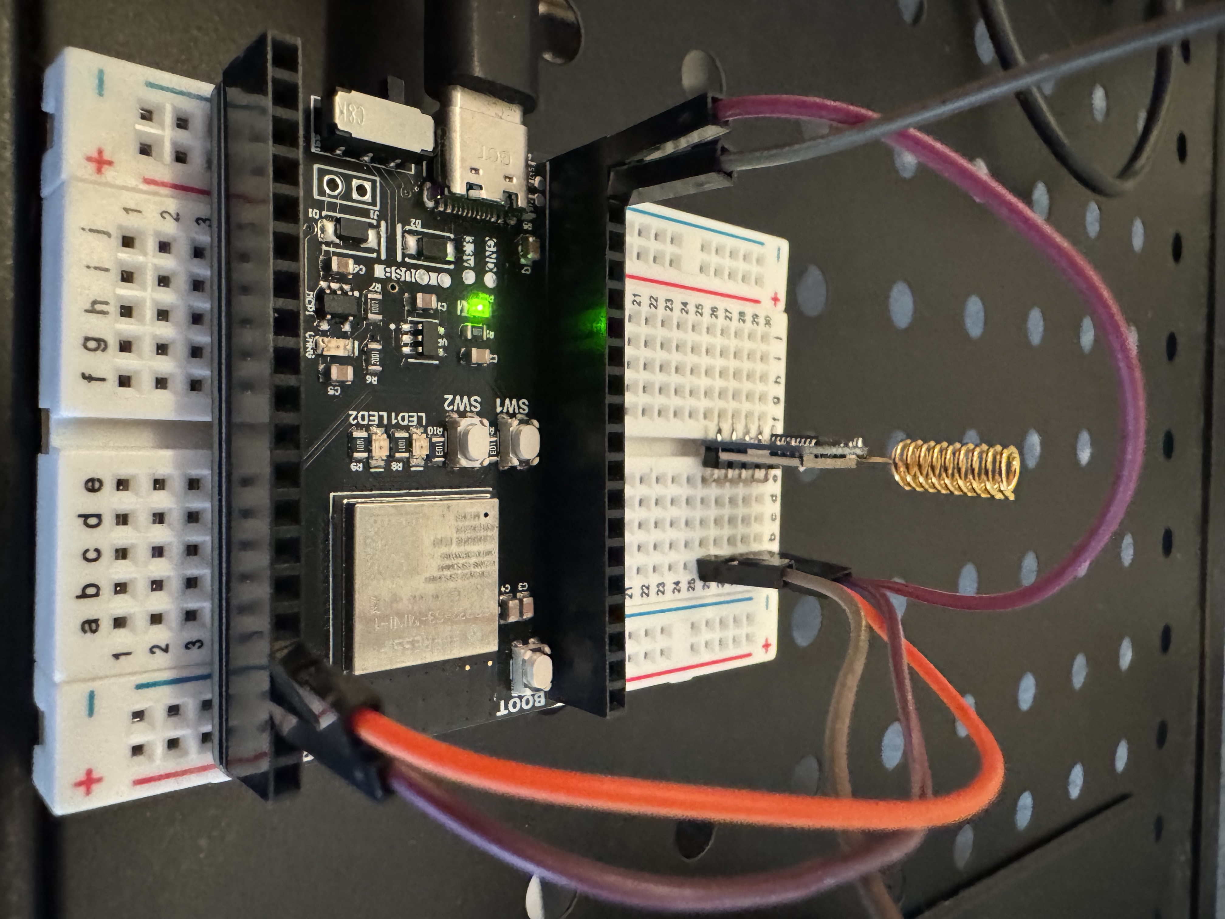
- Place the ESP32 S3 Mini 1 on a breadboard with the USB-C port facing outward for easy access.
- Place the RYLR993 module on the second half of the breadboard or nearby, keeping the pins easy to reach.
- Connect the GND pin on the ESP32 to the GND pin on the RYLR993.
- Connect the 3.3V pin on the ESP32 to the VDD pin on the RYLR993.
- Connect the TX0 pin on the ESP32 to the RXD pin on the RYLR993.
- Connect the RX0 pin on the ESP32 to the TXD pin on the RYLR993.
- Leave the RST pin on the RYLR993 unconnected. It is not used in this setup.
- Double check the connections for each wire to avoid reversed or loose pins.
Repeat these steps for the second ESP32 and second LoRa module using the second breadboard.
Make sure both boards are connected to power either through your computer or a USB-C power bank before continuing.
Part 02: Sending a Basic Message with AT Commands
Introduction
Now you’ll test your hardware setup using basic AT commands. This confirms both modules are responding and able to communicate with each other before moving on to Arduino code.
Objective
- Open the Arduino Serial Monitor and connect to one ESP32
- Send AT commands to confirm the RYLR993 module is responsive
- Use AT commands to transmit a basic message
- Check that the second LoRa module receives the message while powered externally
Background Information
The RYLR993 LoRa module is controlled through a set of AT commands sent over a serial connection. These commands are typed directly into the Arduino Serial Monitor. Once received, the module will respond with confirmation messages like OK, +READY, or +RCV.
Each module has a unique address and communicates by sending data to the address of another module. To test basic messaging, one ESP32 will be connected to the computer and used to send commands. The second ESP32 will be powered separately and should receive the message if everything is wired correctly.
This step confirms that the modules are powered, paired, and able to transmit data wirelessly.
Components
- 1 ESP32 S3 Mini 1 connected to a computer
- 1 ESP32 S3 Mini 1 powered by a USB-C power bank
- 2 RYLR993 LoRa modules
- 2 Breadboards
- 8 Jumper Wires
- 2 USB-C cables
- Arduino IDE with Serial Monitor open
Instructional
Make sure both ESP32 boards are fully wired and powered.
One should be connected to the computer. The other should be powered by a USB-C power bank.Open Arduino IDE.
Go to Tools → Port and select the port connected to the ESP32.Open the Serial Monitor (top right corner or Tools → Serial Monitor).
Set the baud rate at the bottom of the Serial Monitor to 9600 baud. Choose Both NL & CR for line endings.Type and enter the following command into the input box:
ATThe module should reply with:
OKThis confirms the module is powered and responding.
Check the current address of the module:
AT+ADDRESS=?This should return a number like
+ADDRESS=0.
Set the address if needed:AT+ADDRESS=1Confirm the other module is set to a different address (for example, 2). You can set it in the same way by connecting the second ESP32 to your computer temporarily and repeating the above steps.
Send a test message to the second module using:
AT+SEND=2,5,HELLOThis sends the string
HELLOto address 2 with a length of 5.If everything is set up correctly, the second ESP32’s module will receive the message. If the receiving board is connected to Serial Monitor, it will print something like:
+RCV=2,5,HELLO
If no response is received, check that the modules are on different addresses, powered, and wired correctly. You can also refer to the external configuration guide for more help. RYLR993 Configuration Guide (PDF)
Part 03: Writing Arduino Code to Send and Receive LoRa Messages
Introduction
Here you’ll learn to automate LoRa communication using Arduino code. Instead of typing commands by hand, the ESP32 boards will automatically send and receive messages, making your project practical for real world applications.
Objective
- Write Arduino code that sends a LoRa message from one ESP32
- Write code on the second ESP32 to receive the message
- Turn the onboard LED on or off based on the message received
- Run the system without using the Serial Monitor
Background Information
Each ESP32 S3 Mini 1 can run Arduino code that sends and receives messages through its connected RYLR993 module. The modules communicate using AT commands over a serial connection. By sending these commands from inside the Arduino code instead of typing them manually, the devices can run on their own without using the Serial Monitor.
The receiving ESP32 will look for messages that contain the letter “H” or “L”. If it sees “H”, it will turn the onboard LED on. If it sees “L”, it will turn the LED off. This is a simple way to confirm that wireless communication is working and that the receiver is interpreting the message correctly.
Components
- 2 ESP32 S3 Mini 1 boards
- 2 RYLR993 LoRa modules
- 2 Breadboards
- 10 Jumper Wires
- 2 USB-C cables
- 1 USB-C power bank or second USB-C port for power
- Arduino IDE with both sender and receiver code uploaded
Instructional
Step 1: Upload the Sender Code
On the first ESP32, upload the following code. It repeatedly sends “H” and “L” to the LoRa module at address 2 every five seconds.
void setup() {
  Serial.begin(9600);
  delay(100);
}

void loop() {
  Serial.println("AT+SEND=2,1,H");
  delay(5000);
  Serial.println("AT+SEND=2,1,L");
  delay(5000);
}
Step 2: Upload the Receiver Code
On the second ESP32, upload this code. It listens for incoming LoRa messages and turns the onboard LED on or off based on the message content.
String incoming;

const int LED = 17;

void setup() {
  pinMode(LED, OUTPUT);
  Serial.begin(9600);
}

void loop() {
  if (Serial.available()) {
    incoming = Serial.readString();
    if (incoming.indexOf("H") >= 0) {
      digitalWrite(LED, HIGH);
    }
    if (incoming.indexOf("L") >= 0) {
      digitalWrite(LED, LOW);
    }
  }
}
Step 3: Power and Run
- Leave the Sender ESP32 connected to the computer
- Connect the Receiver ESP32 to a USB-C power bank
- Watch the onboard LED on the receiver it should turn on and off every 5 seconds as messages are received
This setup shows real-time wireless control without using the Serial Monitor.
Example
Introduction
This example shows how the receiver ESP32 responds to messages from the sender by turning the onboard LED on and off. It uses the Arduino code written in the previous steps.
Example
Once both ESP32 boards are powered and running the correct code, the LED on the receiver should turn on for 5 seconds, then turn off for 5 seconds, repeating continuously. The message “H” turns the LED on, and “L” turns it off. This confirms that LoRa communication is working and the receiver is correctly parsing the message.
Analysis
With this setup, your ESP32 boards automatically communicate over LoRa without needing the Serial Monitor. Using an LED gives you a straightforward, visual way to verify that everything’s working correctly.
Additional Resources
Useful Links
Troubleshooting
If your LoRa modules aren’t communicating, first check your antenna connections. For detailed configuration steps like setting the right frequency, address, and operating mode, refer directly to the following guide. It clearly explains how to verify and correct these settings:
RYLR993 Configuration Troubleshooting Guide
*Credit to Sebastian Campos for the Configuration Troubleshooting Guide
Make sure your wiring matches the recommended TX and RX connections from the guide, and double-check antenna connections carefully.